Table of Contents
Remote Fire Camera via GPIO
Introduction
One of the full projects I want to do is to make a camera slider (not sure what the official name is) so that I can create time lapse videos with some lateral or vertical movement. To do this I have to work out a few things, and one of these is how to fire the camera from the Raspberry Pi.
There are a couple of ways to do this, one is via USB and gphoto, the other is to use the GPIO pins to emulate what the remote shutter release does, and this is the route I will take.
The Hardware
I use Canon equipment, so this guide will be for Canon cameras, however you can easily adapt it to your own camera, if you know the wiring of the remote shutter for your brand, which is the easy bit.
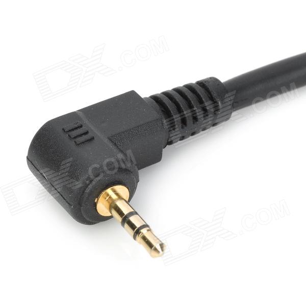
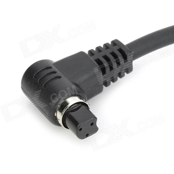
For Canon cameras, there are two connection types that I know of. These can be broadly categorised as one plug (the headphone looking type, but 2.5mm) that goes with most of the cheaper bodies, from XXX down (so 450D, 700D, 1100D etc) and the three pin plug that pretty much gets fitted to anything else. Why Canon use two types I have no idea other than to get people like me, who started on cheap bodies, and worked our way up the range, to buy more accessories.
The Circuit
The circuit for this is really simple, and you will need just a few pennies worth of components to build it. We take two GPIO outputs from the Raspberry Pi and use them to drive an opto-isolator. The output of this is connected to the Canon camera remote shutter port.
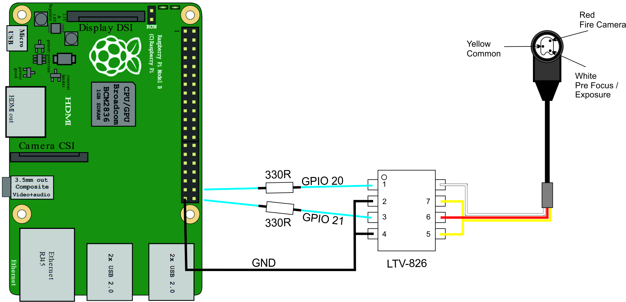
WARNING!!! - The left and right parts of the circuit are independent. Do not connect the common connection on the right to the GND on the left.
In the above circuit, I have connected GPIO Pins 20 and 21 (BCM, not physical pins) to the LTV-826 on pins 1 and 3. LTV Pins 2 & 4 go back to the GND on the Raspberry Pi.
On the output of the LTV-826, Pins 5 & 7 go to the common pin, Pin 8 is the pin I am using to pre-focus the camera and pin 6 fires the camera.
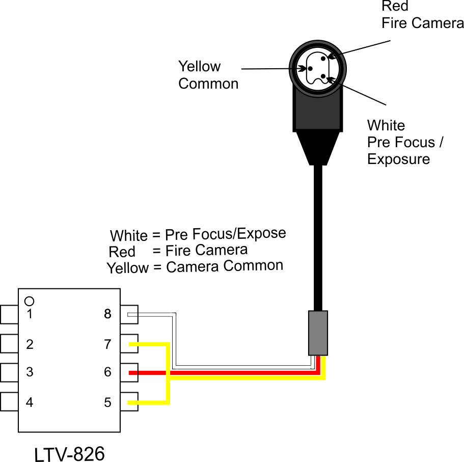
Here we can see a close up of the plug and circuit, I have used Red, White and Yellow wires because I purchased a cheap shutter release cord for my camera, and cut off the button, and these were the wiring colours. Are they standard? don't know.
Below is a diagram of the 2.5mm Jack version.
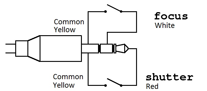
The circuitry is identical, it's just the connector type that changes.
How does this work?
We are using an LTV-826 Opto Coupler to separate the Raspberry Pi GPIO Pins from the Camera Electronics. An Opto Isolator uses an LED/Photocoupler device to allow the input side to switch the output side, but with no connection between the two (unlike say a transistor circuit).
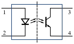
We use a resistor between the output of the GPIO Pin (3.3v remember) to limit the current to the input diode (pin 1 on the Opto-Coupler), this drives the output on pin 4. We use the output pins (3 & 4) like a switch, shorting what is on pin 3 to pin 4 when the input on pin one goes high.
The LTV-826 has two Opto-Isolators in a single 8 pin package.
We need to use two Opto-Isolators, one for the pre-focus stage (the same as when you half press the shutter on your camera) and the other Opto-Isolators to shoot. When you think about this, we need to take the first GPIO pin High, then while keeping that pin high, take the second GPIO pin high, then set them to Low in reverse order.
Simple Test Python Code
Below is a simple Python program that sets two GPIO pins to a high state (with a 1 second delay between them) then sets them both back to low again.
Remember: if you don't set the pins to low after shooting, it's the same as keeping your finger on the shutter button, the camera will just stay in shooting mode (but the shutter will close) and you won't see your preview image or be able to take any more shots.
<sxh [py][; options for SyntaxHighlighter]>
#! /usr/bin/python
# Python Script to fire Canon camera using 2 GPIO pins.
# Version 1.0
# Feb 2017
# Written in Python 2.7
# Import libraries import RPi.GPIO as GPIO import time
#Define numbering system for the IO pins Raspberry Pi. #BCM = GPIO Numbers, Board = Pin Numbers GPIO.setmode(GPIO.BCM)
# Define GPIO ports for use with DSLR gpioPins = (20,21)
# Setup channels for output and set initial values for segment in (gpioPins):
GPIO.setup(segment,GPIO.OUT)
GPIO.output(segment,GPIO.LOW)
# Set GPIO outputs to High, with a delay between the two GPIO outputs. for segment in (gpioPins): # Set first GPIO to High and wait 1s
GPIO.output(segment,GPIO.HIGH)
time.sleep(1)
# Set second GPIO to High and wait 1s
GPIO.output(segment,GPIO.HIGH)
time.sleep(1)
# Ensure Both GPIO Pins are set to low for segment in (gpioPins):
GPIO.output(segment,GPIO.LOW)
GPIO.output(segment,GPIO.LOW)
# Cleanup GPIO
GPIO.cleanup()
</sxh>
Test Python Code With User Input
We have used a simple program to fire the camera, but more useful would be to have some options. The following code prompts the user for two inputs, the first input is the number of desired photos to be taken, the second is the delay between photos.
<sxh [py][; options for SyntaxHighlighter]>
#! /usr/bin/python
# Python Script to fire Canon camera using 2 GPIO pins.
# The user will be asked for two values, one for the number of photos
# and one for the delay between photos.
# Version 2.0
# Feb 2017
# Written in Python 2.7
import RPi.GPIO as GPIO import time
# Ask for user input for number of photos, convert string to int noOfPhotos=int(raw_input(“How Many Photos? ”)) print “you entered”, noOfPhotos print “”
# Ask for user input for delay between photos, convert string to int photoDelay=int(raw_input(“How Many Seconds between Photos? ”)) print “you entered”, photoDelay print “” # Compensate for the 0.5s of delay in gpio loop (settling time) photoDelay += -0.5
# Define numbering system for the IO pins Raspberry Pi GPIO.setmode(GPIO.BCM)
# Define GPIO ports for use with DSLR gpioPins = (20,21)
# Setup channels for output and set initial values for setPin in (gpioPins):
GPIO.setup(setPin,GPIO.OUT)
GPIO.output(setPin,GPIO.LOW)
# setup a loop for the number of photos the user entered (noOfPhotos) while True:
    print "Photo Number ", noOfPhotos

    for setPin in (gpioPins):
    # Set first GPIO to High and wait 0.25s
      GPIO.output(setPin,GPIO.HIGH)
      time.sleep(0.25)
    # Set second GPIO to High and wait 0.25s (just to settle)
      GPIO.output(setPin,GPIO.HIGH)
      time.sleep(0.25)
    # Ensure GPIO Pins are set to low
    for setPin in (gpioPins):
      GPIO.output(setPin,GPIO.LOW)
      GPIO.output(setPin,GPIO.LOW)
    # decrement noOfPhotos
    time.sleep(photoDelay)
    noOfPhotos += -1
    # stop when noOfPhotos is equal to zero
    if noOfPhotos == 0:
        break
# Cleanup GPIO
GPIO.cleanup()
</sxh>
See it in Action
Well here is a short video of me running the code, seeing the camera take the shot and then the image coming up on the preview screen. Once you have got this far, you can now expand the software to do whatever you want.
This code will form the start of my Raspberry Pi Intervalometer. This will be a great tool for static time lapse photography. Once this is done then I can move on to my camera slider project. However the actual slide rails for this will I think take me some time.

