Table of Contents
How to use a Stepper Motor
Introduction
I have in mind a project for my camera work, a motorised camera slider that will allow me to take time-lapse with some element of movement, before I start to build any hardware, I want to ensure that I can both drive a motor, and fire the camera (this will come later).
There are many tutorials out their regarding stepper motors and the Raspberry Pi, while that means there is a lot of useful information, it can be quite a minefield as well.
This page is solely devoted to just using a stepper motor, the other elements will be covered in later updates on separate pages.
The Stepper Motor
A stepper motor contains several coils (depending on the type) that can be 'energised' in a pattern to produce movement, unlike a motor that just spins constantly. Stepper Motors are used where some degree of accuracy in movement is required. For example, getting a normal (non stepper) motor to only spin for a 1/4 turn would be very tricky. A stepper motor can be 'stepped' a set number of times, this gives it much greater accuracy and repeatable results.
There are many types of stepper motor, and the way they are driven falls in to two categories:
  Unipolar
  Bipolar
Unipolar vs. Bipolar
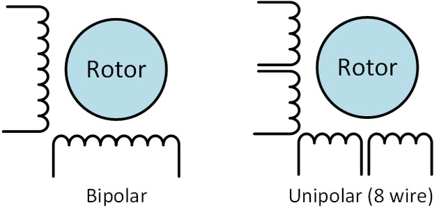
Unipolar drivers always energize the phases in the same way. One lead, the “common” lead, will always be negative. The other lead will always be positive. Unipolar drivers can be implemented with simple transistor circuitry. The disadvantage is that there is less available torque because only half of the coils can be energized at a time.
Bipolar drivers use H-bridge circuitry to actually reverse the current flow through the phases. By energizing the phases with alternating the polarity, all the coils can be put to work turning the motor.
A two phase bipolar motor has 2 groups of coils. A 4 phase unipolar motor has 4. A 2-phase bipolar motor will have 4 wires - 2 for each phase. Some motors come with flexible wiring that allows you to run the motor as either bipolar or unipolar.
5-Wire Motor
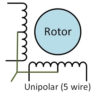
This style is common in smaller unipolar motors. All of the common coil wires are tied together internally abd brought out as a 5th wire. This motor can only be driven as a unipolar motor. This is the type of Stepper Motor that I am using in this example.
28BYJ-48
The 28BYJ-48 is a very common Stepper Motor available on eBay, they are extremely cheap, and if you don't mind the wait while they are shipped from China, then you can get four of them for well under £10 (under £7 last time I looked).
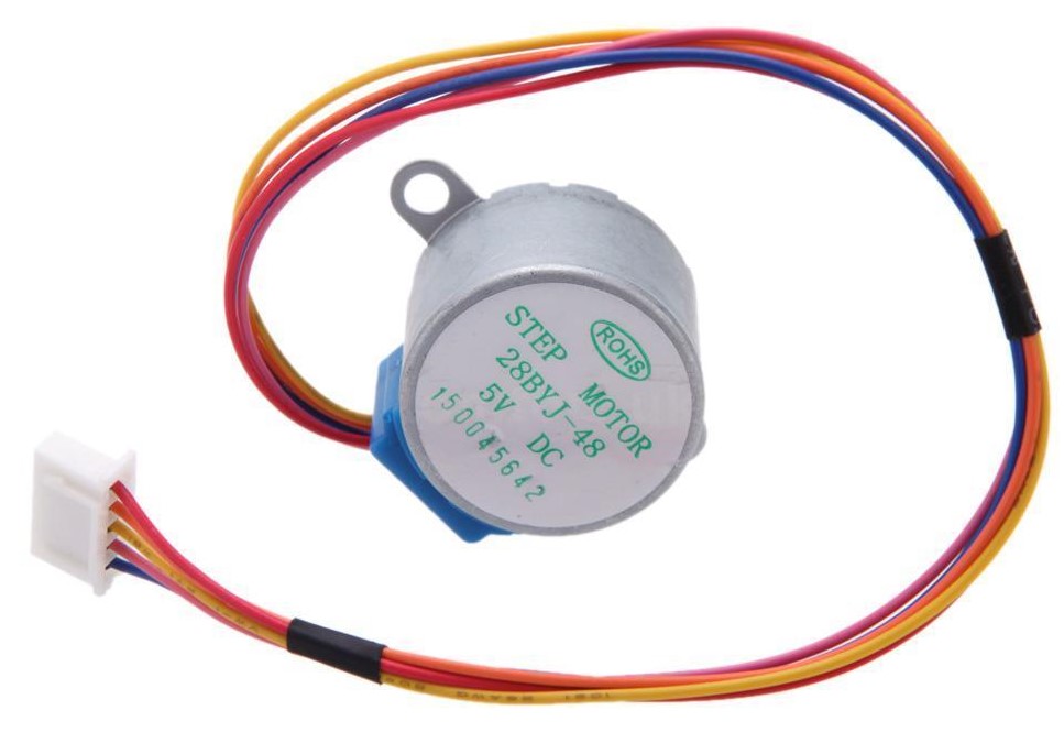
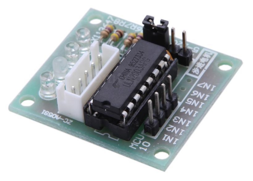
This is the five wire type mentioned above. The Stepper motor comes with a little driver board, normally ULN2003 based, this board has four LEDs so you can see the drive lines go high and low, very handy for troubleshooting.
The ULN2003 driver board has four connections for the coil drivers (four GPIO connections) and a GND and +VCC (5v-12v) connections.
Specification

Motor Type                Unipolar stepper motor
Connection Type           5 Wire Connection (to the motor controller)
Voltage                   5-12 Volts DC
Frequency                 100 Hz
Step mode                 Half-step mode recommended (8 step control signal sequence)

Step angle                Half-step mode: 8 step control signal sequence (recommended) 5.625 degrees per step / 64
                          steps per one revolution of the internal motor shaftFull Step mode: 4 step control
                          signal sequence 11.25 degrees per step / 32 steps per one revolution of the internal
                          motor shaft

Gear ratio                Manufacturer specifies 64:1. Some patient and diligent people on the Arduino
                          forums have disassembled the gear train of these little motors and determined that
                          the exact gear ratio is in fact 63.68395:1. My observations confirm their findings.

                          This means that in the recommended half-step mode we will have:64 steps per motor
                          rotation x 63.684 gear ratio = 4076 steps per full revolution (approximately).

Wiring to the ULN2003A    (Blue), B (Pink), C (Yellow), D (Orange), E (Red, Mid-Point)
Weight                    30g
Stepper Motor Connections
The stepper motor I am using in this example has five wires, one is for the +Ve voltage, the other four are for the two coils. The four coil wires will be connected to the Raspberry Pi GPIO pins.
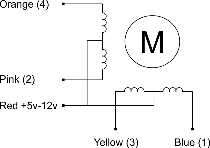
The coils have to be activated in the correct order, or you will find that the stepper motor is slow, has little torque, won't move at all or just gets really hot.
The table below outlines the correct order that the coils should be used in.

Don't connect the Stepper Motor directly to the GPIO pins, they cannot provide enough current and you will likely break your Raspberry Pi.
The driver board that comes with the Stepper Motor is contains a ULN2003A chip. Sometimes it is a discrete version, sometimes it is surface mounted. Both operate the same so don't worry.
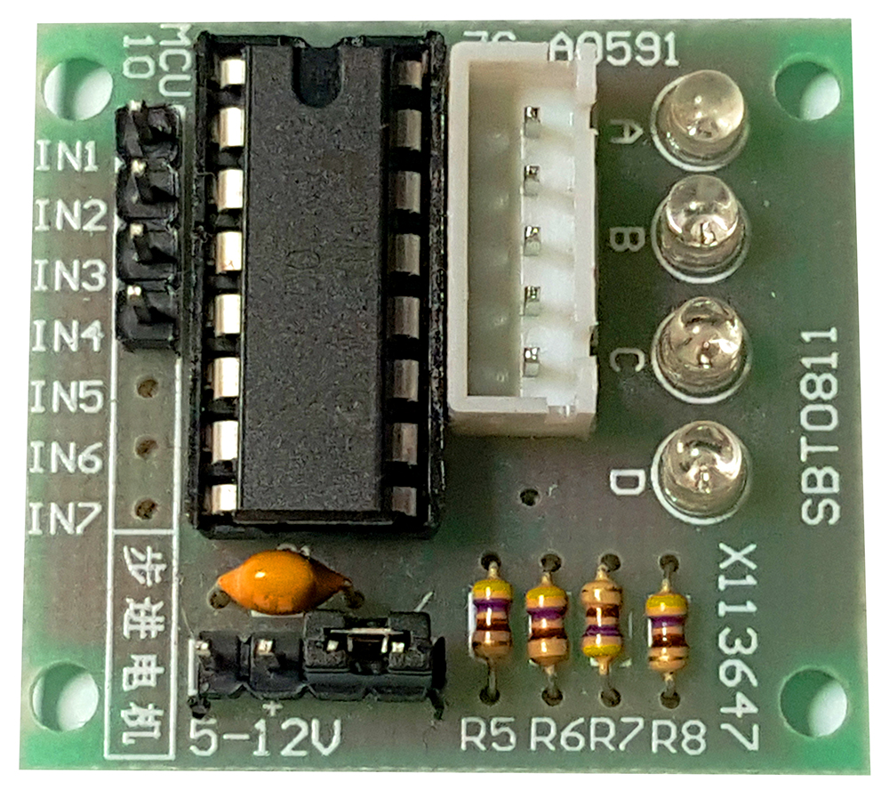
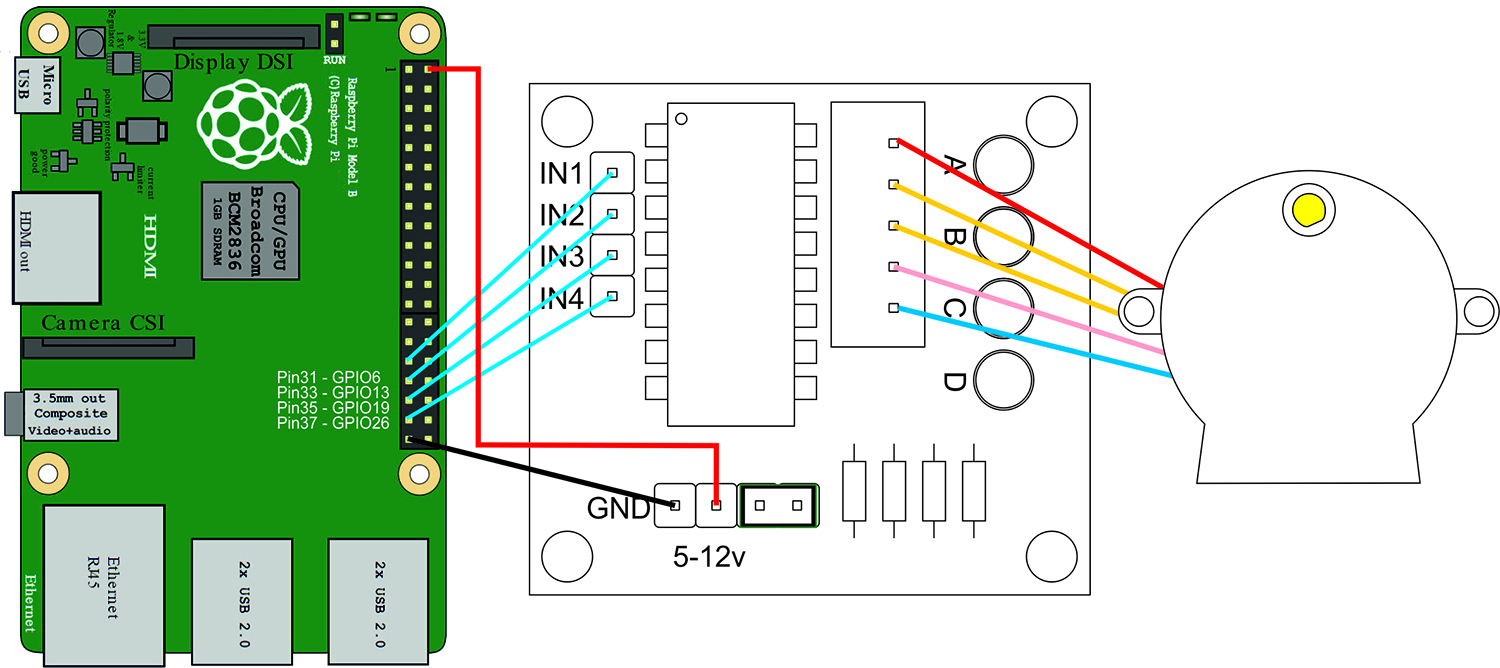
The IN1-IN4 are the connections to the Raspberry Pi GPIO Pins. There is a Gnd and +Ve connection below the INx Pins. The white connector is for the Stepper Motor header, and the four LEDs show you which IN1-IN4 phases are present at any one time (under normal operation these flash so fast they all look they are on, but you can slow this down).
Complete Wiring Diagram
Below are all the connections for the Raspberry Pi, the Stepper Motor and Power. You can use whatever GPIO pins you prefer, you just need to change them in the Python Code. I have used these four connections because the LCD Screen I wish to use with the final project uses some of the other GPIO connections above.
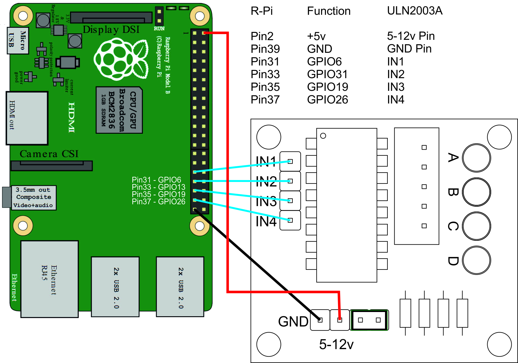
Yep, six wires is all we need. If you are using the same stepper motor as in this example (the 28BYJ-48) then the total current draw of your Pi will be around 500mA (depending on what you have plugged in). This is will within the 1Amp you can get out of the 5V supply.
If you plan to run several stepper motors, then you will need a separate 5V supply (split the 5v in to the Pi) or you will possibly burn out the Raspberry Pi.
Python Code
Now that all the hardware connections are complete we can move on to the Python code. The code will do a couple of main tasks, these are to activate the Stepper Motor coils in the correct sequence, and to have some delay, so that the stepper motor rotor can have time to move before the next sequence.
Firstly, here is the code, the breakdown of the code is further down this page.
<sxh [py][; options for SyntaxHighlighter]>
#!/usr/bin/python
# Written in Python 2.7
# Import required libraries import sys import time import RPi.GPIO as GPIO
# Use BCM GPIO references # instead of physical pin numbers GPIO.setmode(GPIO.BCM)
# Define GPIO signals to use # Physical pins 6,13,19,26 StepPins = [6,13,19,26]
# Set all pins as output for pin in StepPins:
print "Setup pins"
GPIO.setup(pin,GPIO.OUT)
GPIO.output(pin, False)
Seq = 1,0,0,0], [1,1,0,0], [0,1,0,0], [0,1,1,0], [0,0,1,0], [0,0,1,1], [0,0,0,1], [1,0,0,1
StepCount = len(Seq) StepDir = 1 # Set to 1 or 2 for clockwise
# Set to -1 or -2 for anti-clockwise
# Read wait time from command line if len(sys.argv)>1:
WaitTime = int(sys.argv[1])/float(1000)
else:
WaitTime = 10/float(1000)
# Initialise variables StepCounter = 0
# Start main loop while True:
# print StepCounter, # print Seq[StepCounter]
for pin in range(0,4):
  xpin=StepPins[pin]# Get GPIO
  if Seq[StepCounter][pin]!=0:
# print “ Enable GPIO %i” %(xpin)
    GPIO.output(xpin, True)
  else:
    GPIO.output(xpin, False)
StepCounter += StepDir
# If we reach the end of the sequence
# start again
if (StepCounter>=StepCount):
  StepCounter = 0
if (StepCounter<0):
  StepCounter = StepCount+StepDir
# Wait before moving on
time.sleep(WaitTime)
</sxh>
Python Code Examination
Below we have broken the Python code down in to sections to explain each part of the program.
The first part is where we import the libraries to allow python to use the GPIO (rpi.gpio), the time functions (sleep) and system functions (sys)
<sxh [py][; options for SyntaxHighlighter]>
import sys
import time
import RPi.GPIO as GPIO
</file>
The next line tells python that we are referring to the GPIO in terms of its GPIO
numbering (BCM) not the physical pin numbers (BOARD)
<sxh [py][; options for SyntaxHighlighter]>
GPIO.setmode(GPIO.BCM)
</file>
Next we need to define which GPIO connections we are using (the GPIOxx numbers).
This project requires four GPIO connections, and this tells Python which ones we are using.
<sxh [py][; options for SyntaxHighlighter]>
StepPins = [6,13,19,26]
</sxh>
The numbers 6,13,19 & 26 refer to GPIO6, GPIO13, GPIO19 and GPIO26.
Now we have to configure the GPIO pin modes.
<sxh [py][; options for SyntaxHighlighter]>
for pin in StepPins:
print "Setup pins"
GPIO.setup(pin,GPIO.OUT)
GPIO.output(pin, False)
</sxh>
We start a loop, and step through all the values in the previous section (StepPins = [6,13,19,26]) and set each pin mode as an output (GPIO.setup(pin,GPIO.OUT)) and set the pins low (GPIO.output(pin, False)).
Now we define a List that contains a list of values.
<sxh [py][; options for SyntaxHighlighter]>
Seq = 1,0,0,0],
[1,1,0,0],
[0,1,0,0],
[0,1,1,0],
[0,0,1,0],
[0,0,1,1],
[0,0,0,1],
[1,0,0,1
</sxh>
There are four binary values, these correspond to the GPIO outputs. The list is used as an order to turn the GPIO outputs on and off at the correct time (in the correct sequence). If this sequence is incorrect, or the stepper motor is wired incorrectly, then you will get slow or zero movement in the stepper motor (and it might get pretty hot).
The next line defines a counter, the length of the counter is set to the number of entries in the dictionary called seq. In this case it is 8.
<sxh [py][; options for SyntaxHighlighter]>
StepCount = len(Seq)
</sxh>
The next line sets the direction.
<sxh [py][; options for SyntaxHighlighter]>
StepDir = 1 # Set to 1 or 2 for clockwise
# Set to -1 or -2 for anti-clockwise
</sxh>
Use +1 for Anti-Clockwise and -1 for Clockwise
The next section prompts the user for a numerical input.
<sxh [py][; options for SyntaxHighlighter]>
if len(sys.argv)>1:
WaitTime = int(sys.argv[1])/float(1000)
else:
WaitTime = 10/float(1000)
</sxh>
This section then takes that input and if it is greater than 1 divides it by 1000 (so 2 would = 0.002). If it is not >1 then it is just calculated to 0.001. If you enter 0 here, the WaitTime will be zero, and the Stepper Motor rotor will not turn because the coils are changing state too fast.
This line simply ensure that the variable StepCounter starts at zero.
<sxh [py][; options for SyntaxHighlighter]>
StepCounter = 0
</sxh>
Start a loop
<sxh [py][; options for SyntaxHighlighter]>
while True:
</sxh>
While True simple means loop unconditionally forever.
These next two lines are commented out, they print to the screen the values of the StepCounter and the Seq. You can uncomment these if you are having issues, as they are useful for debugging.
<sxh [py][; options for SyntaxHighlighter]># print StepCounter,
# print Seq[StepCounter]
</sxh>
When you uncomment these lines, you will notice that the rotor will run a lot slower, as this uses way more CPU time (well on the Pi Zero that is the effect anyway).
The next section is a for loop that goes through each list [1,0,0,1] and sets each GPIO Pin [6,13,19,26] accordingly. So the first Seq list item is [1,0,0,0]. So this loop reads each of the four parts of this list element, and sets GPIO Pin 6 to High, and Pins 13,19,26 to Low)
<sxh [py][; options for SyntaxHighlighter]>
for pin in range(0,4):
  xpin=StepPins[pin]# Get GPIO
  if Seq[StepCounter][pin]!=0:
# print “ Enable GPIO %i” %(xpin)
    GPIO.output(xpin, True)
  else:
    GPIO.output(xpin, False)
</sxh>
For fault finding there is an embedded print statement that will output the Seq to the screen (so [1,0,0,1] for example). Uncomment this for fault finding. As previously mentioned, this may impact your Stepper Motor rotor speed.
This next line does quite a lot in real terms.
<sxh [py][; options for SyntaxHighlighter]>
StepCounter += StepDir
</sxh>
Firstly StepCounter (goes from 0-7 because our list is 8 elements long) is affected by the value of StepDir (where you set it to +1 or -1) StepCounter += StepDir means take the value of StepCounter, and add/subtract 1 to it, and make StepCounter the new value.
So if StepDir is set to +1 for Anti-Clockwise rotation, then StepCounter (starts at zero remember) will be StepCounter +=1, which is the same as saying StepCounter = StepCounter + 1.
The next block of code is waiting for the StepCounter to reach the value of StepCount.
<sxh [py][; options for SyntaxHighlighter]>
if (StepCounter>=StepCount):
  StepCounter = 0
if (StepCounter<0):
  StepCounter = StepCount+StepDir
</sxh>
Remember, earlier in this program we said StepCount = len(Seq) (so in this example where we have 8 elements [1,0,0,1] etc) StepCount will = 7 (0 to 7 is 8).
When StepCounter is the same value as StepCount, the counter is reset to 0 so that the process resets.
The last line is the sleep statement.
<sxh [py][; options for SyntaxHighlighter]>
time.sleep(WaitTime)
</sxh>
This waits for the value of WaitTime. WaitTime was calculated by dividing the value you entered at the command line when the program started by 1000. So if you entered the value 3, then the WaitTime value is 0.003. So between each coil state change we will wait 3mS.
Stepper Motor in Action
Here is a short video so that you can see my stepper motor in action. The stepper motor is being driven by a Raspberry Pi Zero. At the time of writing I am achieving a rotation of 12 rpm approx.
Please note that this video has no audio.
Here is a photograph of the breadboard prototype:
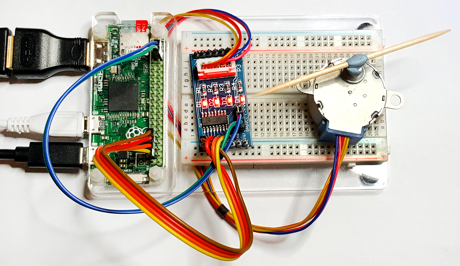
As it can be seen, this is a very simple project, that has lots of applications and is fun to play with.
Troubleshooting
So if you are reading this it's probably all gone wrong. Luckily there are a few things we can do to help understand the issue.
1. Check wiring. Did you use the GPIO numbers, or the GPIO Pin numbers? Check this again.

2. Slow down the program, when you run it, use a value of say 5000. This will give you 5 seconds between
   coil state changes. This means you can see the LEDs on the diver board change, and they should match
   the list in the Seq.

3. Uncomment the print statements in the code, this will write the events to the screen.

4. If your motor runs, but its not smooth, or really slow, you either used a poor delay value (try 1, 2 or 3)
   or your coils are wired in the incorrect order.

5. If you used different GPIO pins to me, did you change the line in the code that tells the Raspberry Pi
   what GPIO pins you are using? (StepPins = [6,13,19,26])
Here is an example of running the program with a change every 1 second.
Here is the output to the screen where the print statements are uncommented.
References
I read many many websites regarding stepper motors and the Raspberry Pi, and I am very grateful to all the people that spent their time documenting their adventures with this technology, below are a few of the sites that I visited to assemble all the information I required for this project.
http://www.instructables.com/id/BYJ48-Stepper-Motor/
http://42bots.com/tutorials/stepper-motor-wiring-how-to/
http://42bots.com/tutorials/28byj-48-stepper-motor-with-uln2003-driver-and-arduino-uno/
https://www.youtube.com/watch?v=Dc16mKFA7Fo&t=1s

