Table of Contents
GPIO Inputs - Button LED Control
In the GPIO LED Control section, we looked at how to crate an output pin on the GPIO and turn it on (3.3v) and of (0v).
In this section we will look at how to create an input pin, that is a GPIO pin that looks for an input (which will be a voltage). When we talk about voltages, the Raspberry Pi only sees a voltage in terms of an on (3.3v) or off (0v). However, other voltages will fall in to either the on or off state, and roughly speaking, these are:
  Off =   0v - 1.2v
   On = 1.3v - 3.3v
Remember, the GPIO pins are 3.3v as they are logic devices, attach more than 3.3v and you might have to buy a new Raspberry Pi!
Pull Up, Pull Down
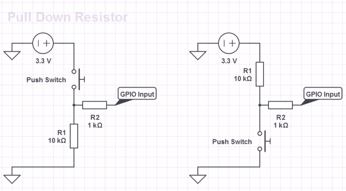
As we know, the value of a GPIO pin can be between 0v - 3.3v, this is a bit of a problem, because we need a pin to be at a known value so we don't get false positives, for this reason the Pi GPIO actually has built in Pull Up and Pull down resistors.

So for any input that we are waiting for a high signal (3.3v) we will use pull down so it stays a 0v, for any pin we are waiting for a low signal (0v) we will use a pull up so it stays at 3.3v (until a button press makes it low)
If you are using your Raspberry Pi via SSH or a Remote Desktop session, you need to enable remote access of the GPIO Pins, instructions for this are here:
From the command line, create a new file for editing:
sudo nano LED-Button.py
You can download the code Here:
  #import modules
  import RPi.GPIO as GPIO    # This imports the GPIO libarary that allows the use of the GPIO pins,
                             # These libraries are built in to Raspbian.

  GPIO.setmode (GPIO.BOARD)  # This sets the GPIO pin numbering. Our LED is connected to Pin 12,
                             # so we can reference it by using BOARD as pin 12. However there is
                             # another option (BCM) where we can reference a pin by it's name, pin
                             # 12 is called GPIO18 (a reference to its place on the chip).

  GPIO.setup(11, GPIO.IN, pull_up_down=GPIO.PUD_DOWN) # setup GPIO Pin 11 as an input, and set
                                                      # the resistor to Pull Down (PUD_DOWN)
                                                      # this is the pin the button is connected to
                                                      # button is connected from pin 11 to the
                                                      # +3.3v pin on the GPIO

  GPIO.setup(12, GPIO.OUT)   # Sets the GPIO pin as output. This is connected to the LED, then
                             # from the LED to 0v via a 330 Ohm resistor.

  GPIO.output(12, 0)         # sets the GPIO Pin 12 to low (so 0v)

  try:
          while True:                             # start a loop
                  if (GPIO.input(11) == 0):       # if GPIO pin 11 is a 0 (Low (0v)) then..
                          GPIO.output(12,0)       # set Pin 12 to 0v (LED Stays off)
                  else:                           # if GPIO pin is anything other than High (3.3v) then..
                          GPIO.output(12,1)       # set Pin 12 to 3.3v (LED comes on)
  except KeyboardInterrupt:                       # if Ctrl-C is pressed, exit loop
          GPIO.cleanup()                          # reset GPIO pins to default state

  #End
The Button in Action
Here is the button turning on the LED
A Small Issue
While this code works without any real problems, because we are in a constant loop, this code is very heavy on CPU load, on the Pi Zero I am using this causes the processer to sit at 100 %, a better method is to use an interrupt
This guide is comprised of information from a youtube video by Gaven MacDonald. Thanks Gaven.
