Table of Contents
Two Line LCD Character Display
Introduction
Note:- Please read this section first, but note that there is a lot more information, including PCB layouts on This Page.
While the title says 2 Line LCD Display, this will actually work for any HD44780 or HD44780 compatible display, of which there are many. You can buy these type of displays from eBay for £3-£5 for a 16×2 (2 lines, 16 characters per line) and there are many uses for them.
While there are a lot of displays around, do try to get one that you can get the datasheet for, or that is clearly labelled on the pins or on the rear of the PCB. Avoid LCDs that have Electro Luminescent backlights, these need fairly high voltage AC Circuits, just plain old LED backlight will be fine.
In this LCD Example, our LCD will be running in 4bit mode. There are other LCDs that run using I2C, these require much less wiring, but the libraries can be harder to obtain.
As well as an LCD, while you are prototyping the circuit, a piece of breadboard and some interconnects that are solderless will be useful as well. If you are using breadboard, then you can use female-male connections, if you wire the LCD directly to the Pi, just use Male-Male (this is a simpler and cheaper solution.
Parts
You will need a Raspberry Pi, I have done this with a Pi-3 and a Pi-Zero and both worked perfectly. For testing use a zero if you can, if you blow it up it's only a fiver, a Pi3 is £30).
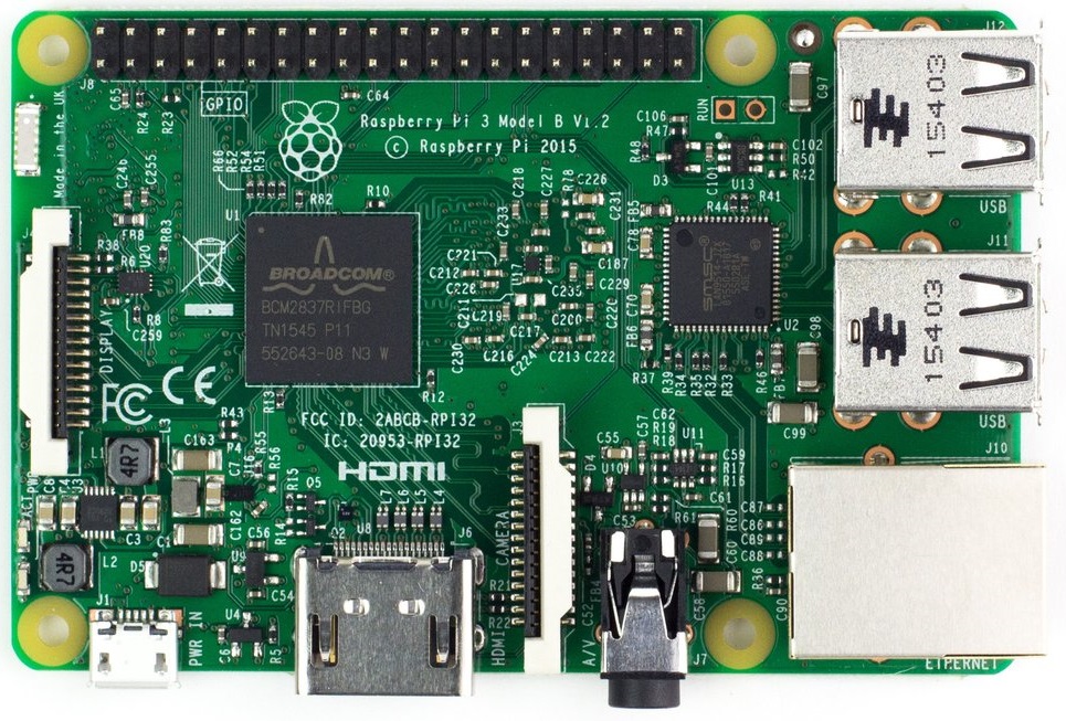
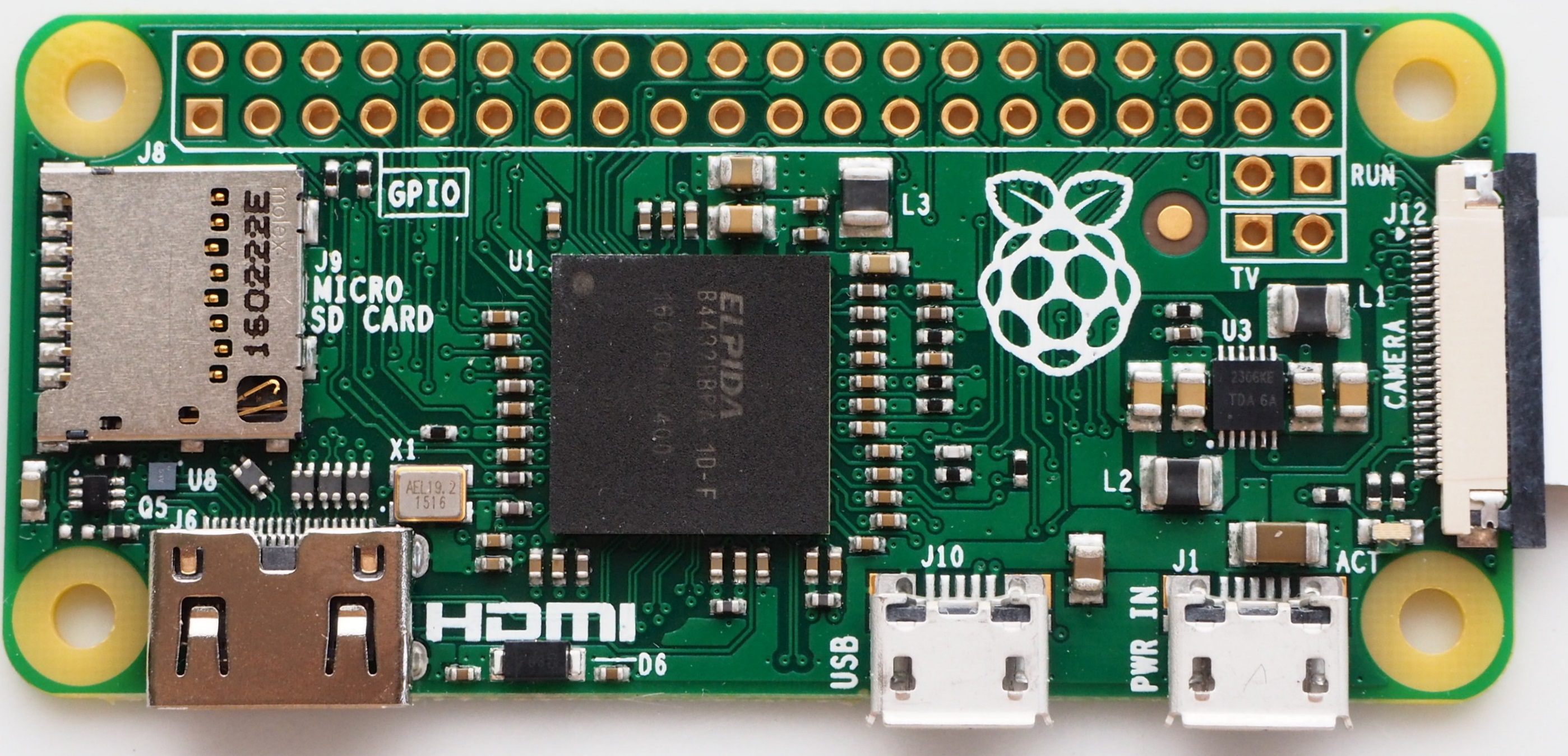
You will need a HD44780 (or compatible) display

Breadboard and Cables
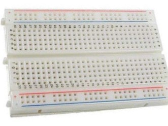
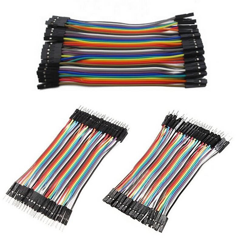
I have not listed everything you will need here, of course you will need the Raspberry Pi, and SD card, you need either Keyboard and Mouse or RDP connection to the Pi etc.
Raspberry Pi Setup
Here is a basic overview of what needs to be done:
1. Download Raspbian image from https://www.raspberrypi.org/
2. Update and Upgrade the Raspberry Pi.
3. Download sample code.
4. Make The Hardware Connections.
5. Test.
Step 1
Go to the Raspberry Pi site (if you haven't already) and download the latest Raspbian. There are instructions there on how to get the Raspbian on to your SD card and boot it up.
If you forgot, or just didn't see it anywhere, the default login for Raspbian (as of the time of writing, we are on Jesse right now):
      user    pi
      pass    Raspberry
Step 2
The basic Raspbian install is nearly always out of date, to update it you must run two commands from the command line:
      sudo apt-get update
      sudo apt-get upgrade
Step 3
This whole project is based on a YouTube video I watched https://www.youtube.com/watch?v=cVdSc8VYVBM
You can also visit this website http://www.rototron.info/lcd-display-tutorial-for-raspberry-pi/
And download this file http://www.rototron.info/wp-content/uploads/LCD-Display_lcd_py.zip
If the site is down, or has moved, then the code is LCD.PY
Step 4
Before you start, power off the Raspberry Pi!
Make the Hardware Connections. Now before you go wild connecting things up, I would like to make you aware of Raspberry Pi pin numbering. Some people when doing a project refer to the Pin No (so they might say connect to Pin 26) where as others use the GPIO Pin No, where they might say connect to GPIO Pin 26 (which is physical pin number 37 on a Pi3 and PiZero).
Ensure you know what ones you are using. I will make it as obvious as I can here. For dereference, check out the next diagram. It shows both Pin and GPIO numbers.
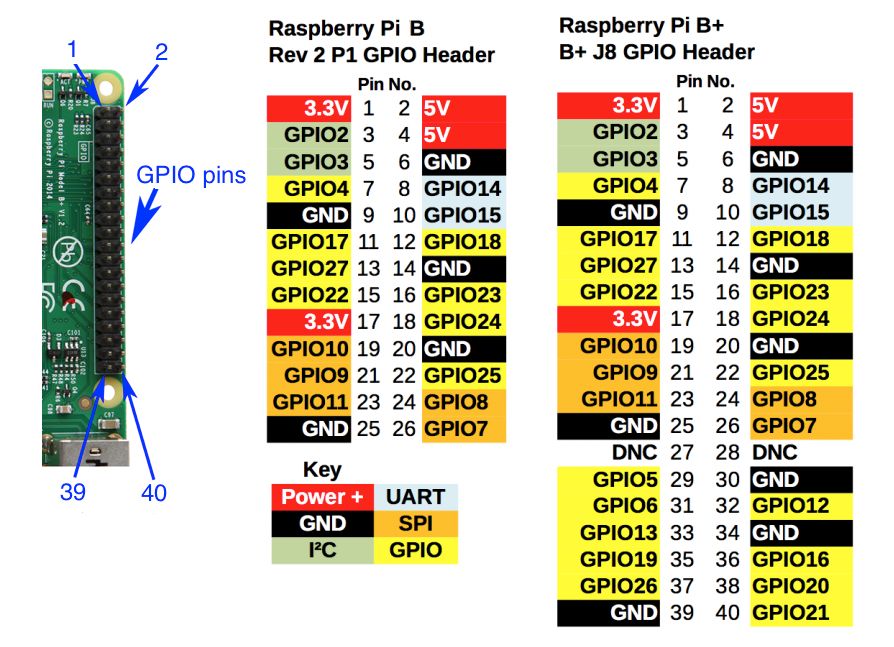
To connect the LCD to the Raspberry Pi will require 12 connections, most of these are power and ground for the LCD, and the rest are control and data lines.
Here is a list of connections
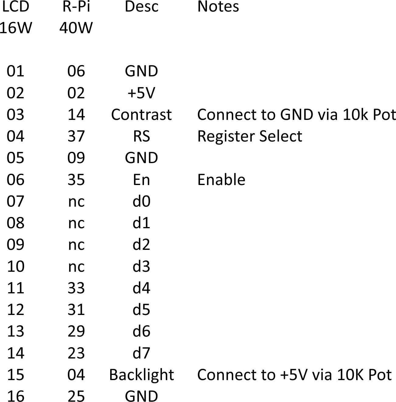
The PIN NUMBERS here are PHYSICAL PINS, not GPIO Numbers. So PIN1 on the LCD goes to PIN6 on the Raspberry Pi
  LCD    R-Pi
   01     06    (or use Pin9 (any GND Pin on the RPI)
   02     02
   03     14    (or any GND pin)
   04     37
   05     09
   06     35
   07     -
   08     -
   09     -
   10     -
   11     33
   12     31
   13     29
   14     23
   15     04    (pin 15 to +5v)
   16     25
On the LCD, Pin 3 and Pin 15 need to go via a 10KOhm Pot, so that you can adjust the backlight brightness (pin 15) and the Text brightness (pin 3).
Once you have made the connections, power on the Raspberry Pi.
Step 5
Once you have downloaded the lcd.py from http://www.rototron.info/lcd-display-tutorial-for-raspberry-pi/ (you can do this from the Raspberry Pi, it means you don't have to copy the files over) Extract the zip file and there are two Python files:
1. lcd.py — This is the one we want.
2. lcd_test.py (or use this one from this wiki Here)
You need to open this file in the Python Editor called IDLE. Open a command window (from the graphical view) and select:
sudo idle lcd.py
This will open the lcd.py in our Python environment.
  NOTE: If you are connected locally, then this is okay. If you are using your Pi via
  remote access, you must  enable remote control of the GPIO ports in the raspi-config utility.
Press F5 to run the program, and your LCD should start up.
While this code seems to work fine, I much prefer to use this code 40x2LCD
This code is for a 40×2 LCD but will work with a 16×2 by modifying the line:
LCD_WIDTH = 40 # Maximum characters per line --- Change the 40 to a value of 16
