Table of Contents
Circuit and PCB layouts
Mar 2017
The Circuit Diagram
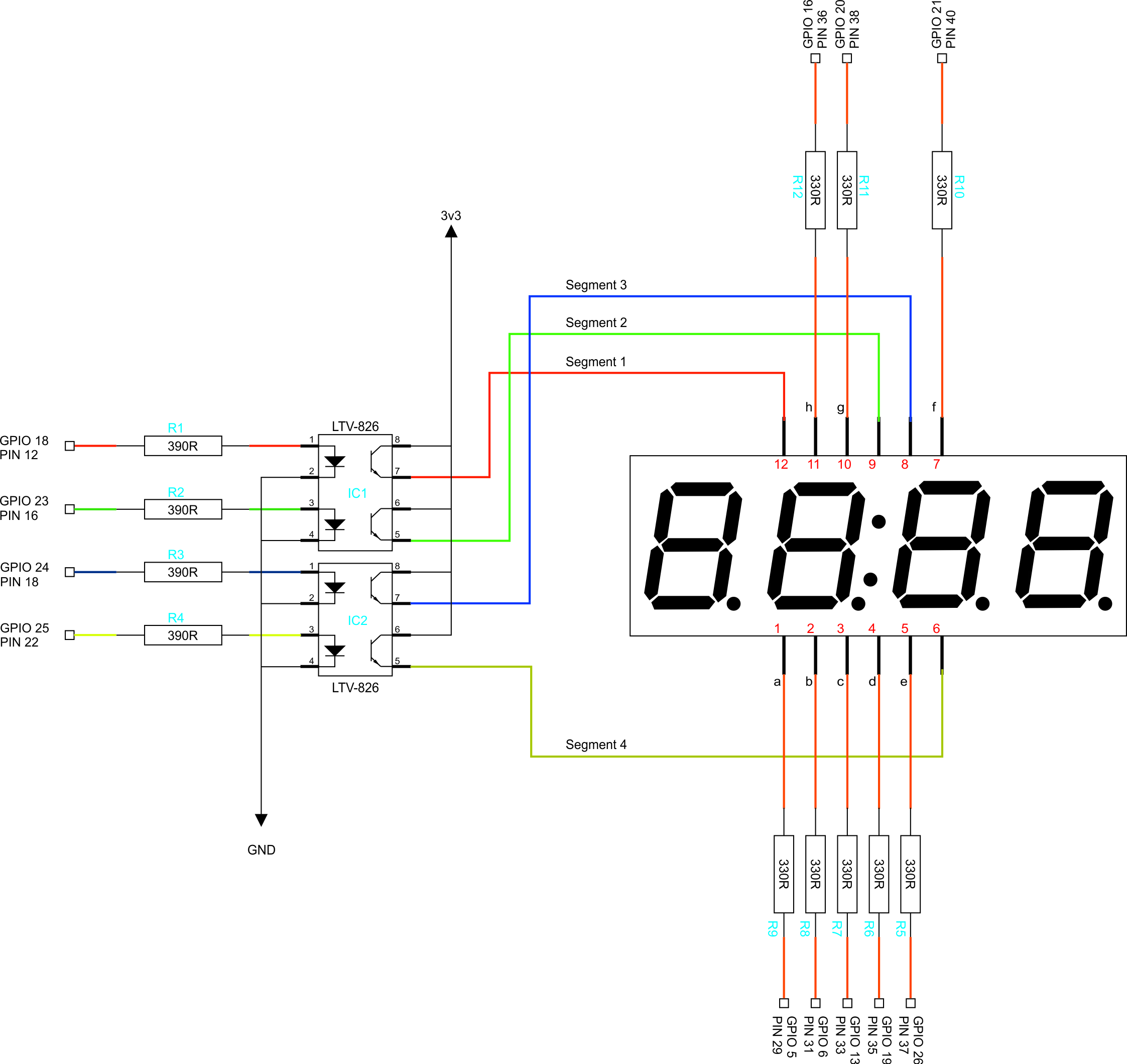
Below is the circuit diagram for the Raspberry Pi NTP Clock. Bear in mind that I am using two Opto Isolators that are 8 pin packages, there are 16 pin packages that have enough connections that you can also use, it's up to you.
Please also remember that this project only uses 3.3v. So yes you do still power the Raspberry Pi with 5v, but circuit only uses the 3v3 pin on the Raspberry Pi, all resistor values reflect the fact that I am using 3v3.
PCB Layout v3.1
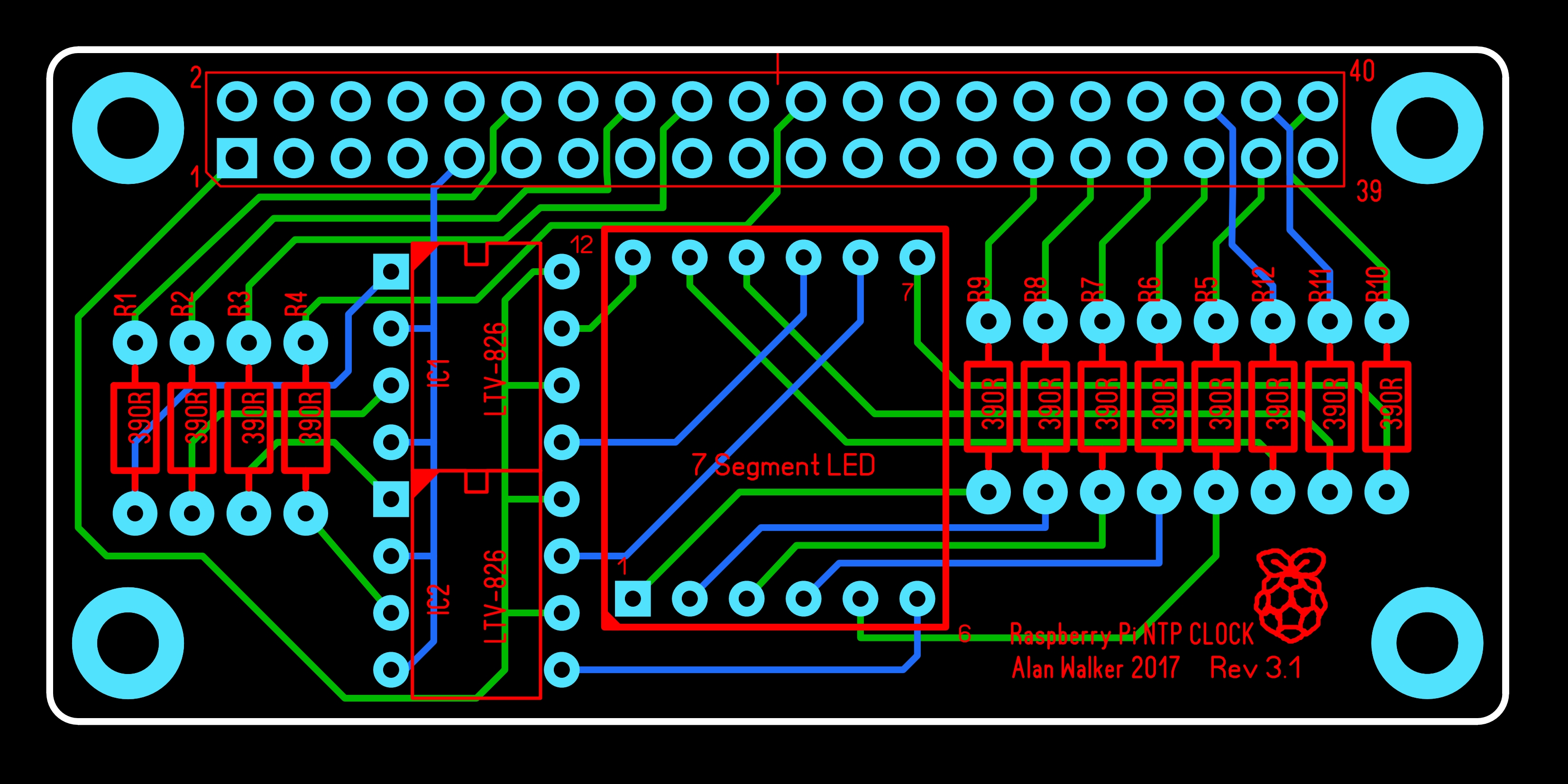
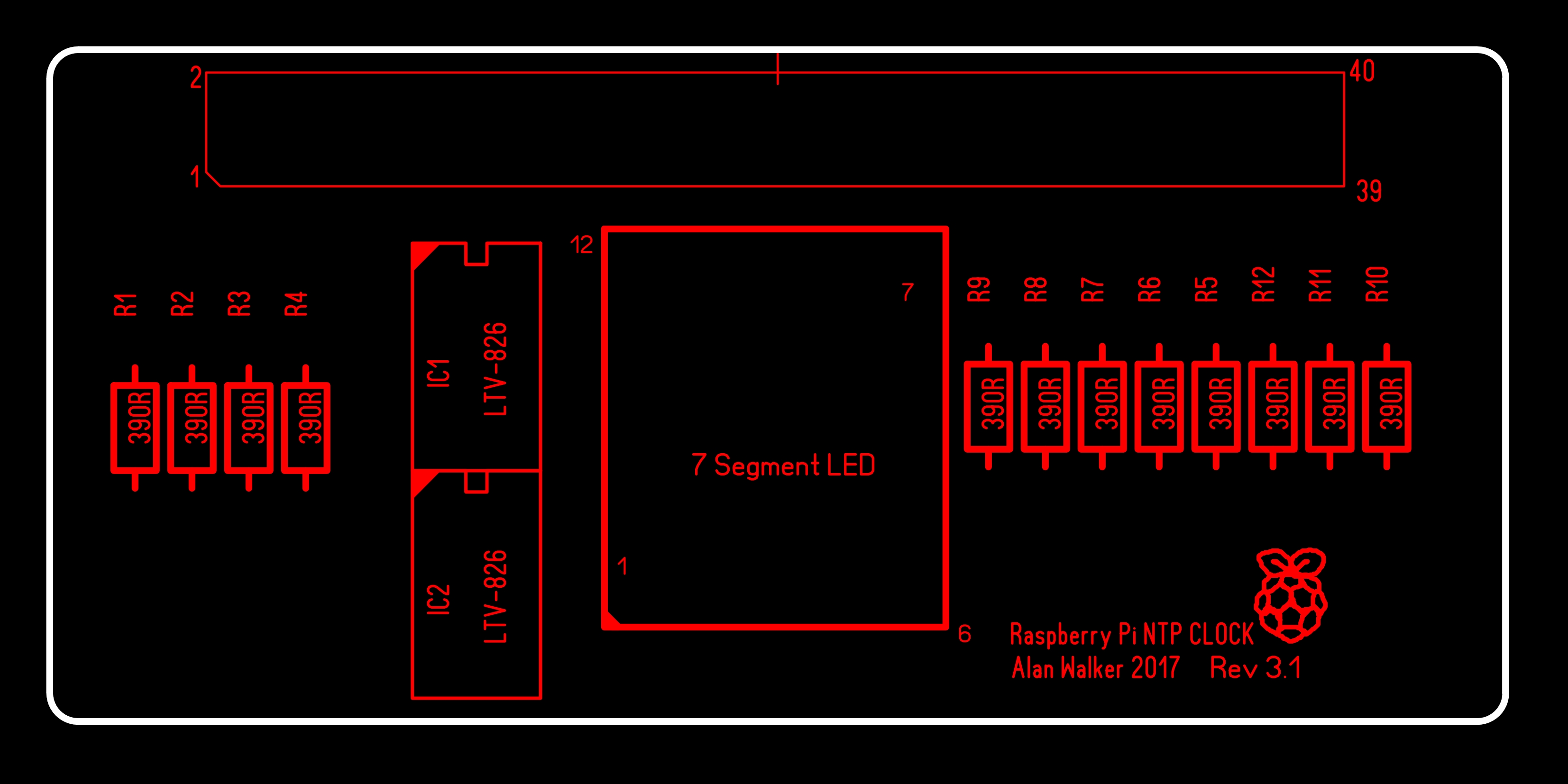
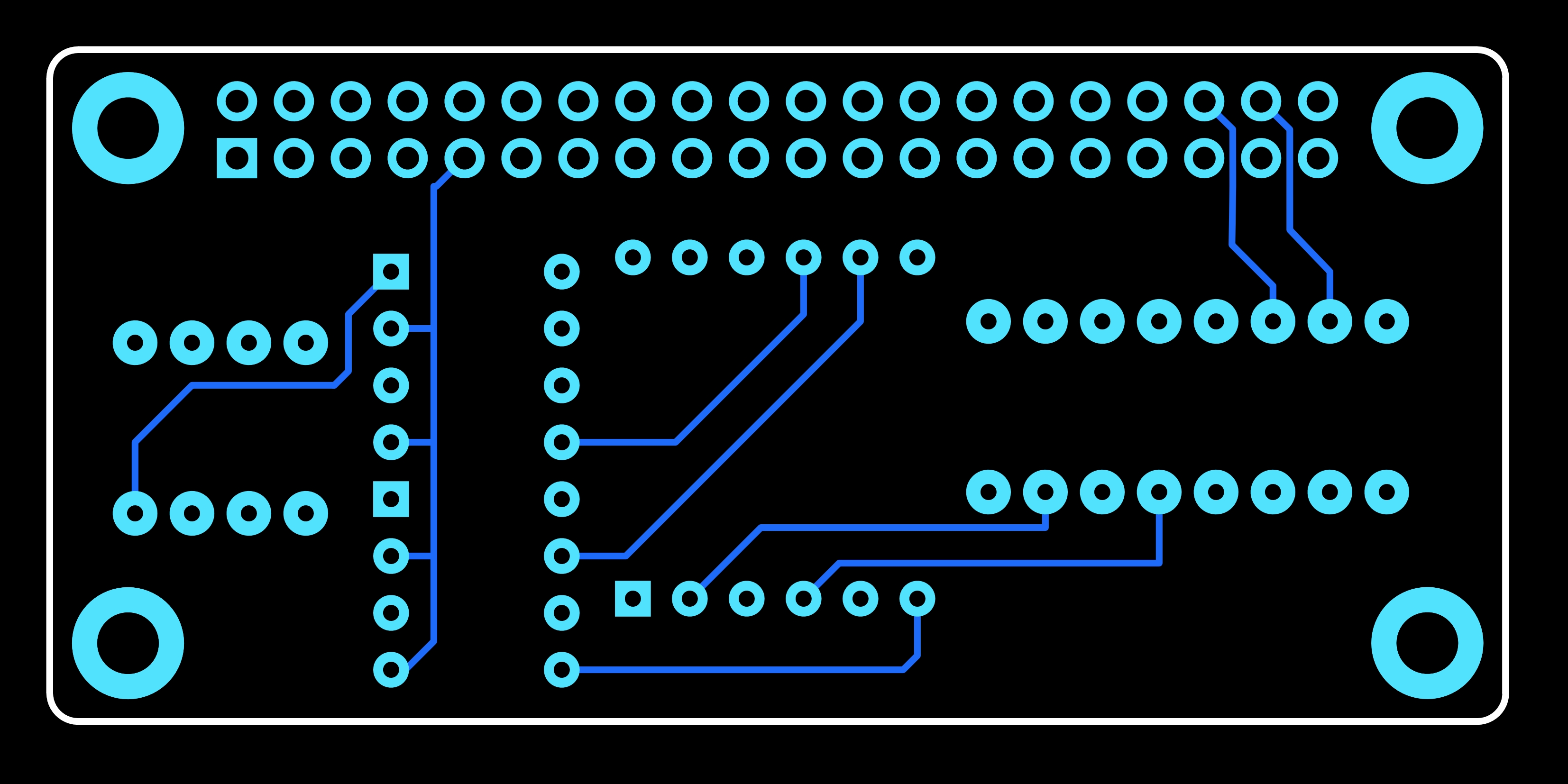
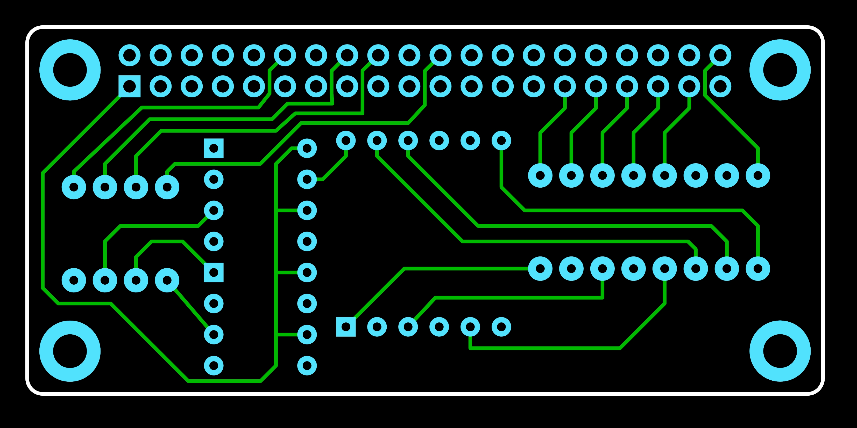
Here is what the PCB layout looks like (from the CAD drawings) I have not had any made yet, so this may be subject to change (I am writing this page Early March 2017).
Full PCB - All Layers
Photo View
Top Layer Silkscreen
Top Layer Copper
Bottom Layer Copper
Outline Layer

If I have created this correctly, the PCB should be exactly the same size as the Raspberry Pi Zero (1, 1.3 and W) which is 65mm x 30mm (excluding edge connectors such as USB and HDMI) and the four corner holes should line up.
Gerber Files
If you wish to get your own PCBs made, you can use the attached Gerber files Here. However I have not had any made myself yet, so you might want to either wait, or create your own PCB.
PCB File
This is the PCB Layout file, produced in software called Sprint Layout v6.0 http://www.abacom-online.de/uk/html/sprint-layout.html. The PCB file can be downloaded Here.
On the Sprint Layout website, you can download a free 'Viewer' for the PCB file so you can print it out. Please check their website for this software (Sprint Layout)

