Table of Contents
VLAN Tagging
Mar 2024
Introduction
In some cases, customers want to use VLAN tagging on our equipment to allow for the control of traffic either upstream or downstream.
This is not available in the GUI, but can be managed from the Linux OS.
In this example we will look at VLAN tagged IP outputs, but the same is possible in reverse for the IP inputs.
Below is what we want to achieve. An IP multicast output on a couple (or more) VLANs that are tagged. All of the VLANs feed in to a trunk port on the switch. Each VLAN output is then available on a separate interface on the switch.
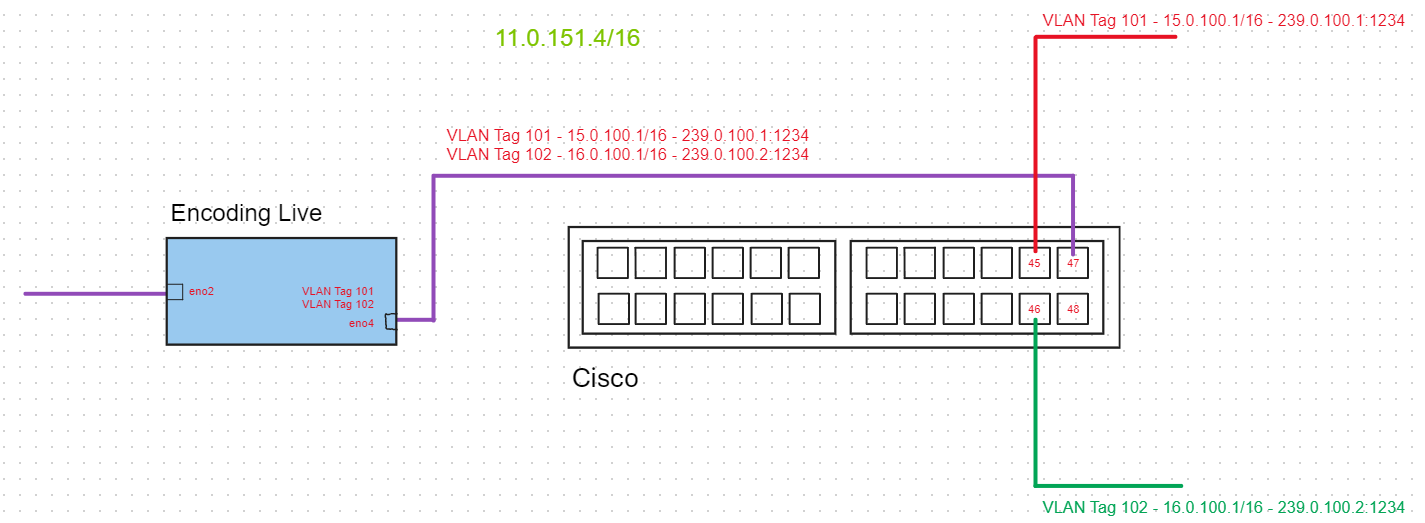
In the above example, the two outputs from the EL, from VLAN101 and VLAN102 are fed in to the Cisco interface 47 which is configured as a trunk port. Then VLAN101 traffic is available on interface 45 on the Cisco, and VLAN102 traffic is available on interface 46 on the Cisco. Interface 46 and 46 are 'Switchports' not trunk ports.
On the Encoding Live in Alma Linux
The first step is for us to setup the VLANs on the Linux OS. These are virtual interfaces which contain both the VLAN ID and IP Address for the virtual interface. We will configure two virtual interfaces here, but you can have more if you require.
Either SSH into the EL or use a KVM and enter the following:
nmtui
nmtui is a graphical tool for creating and editing interfaces in Linux.
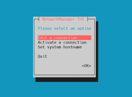
Select Edit a connection
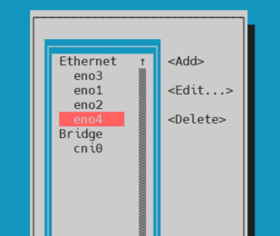
Scroll down to the interface you wish to create the virtual interfaces on (eno4 in this example)
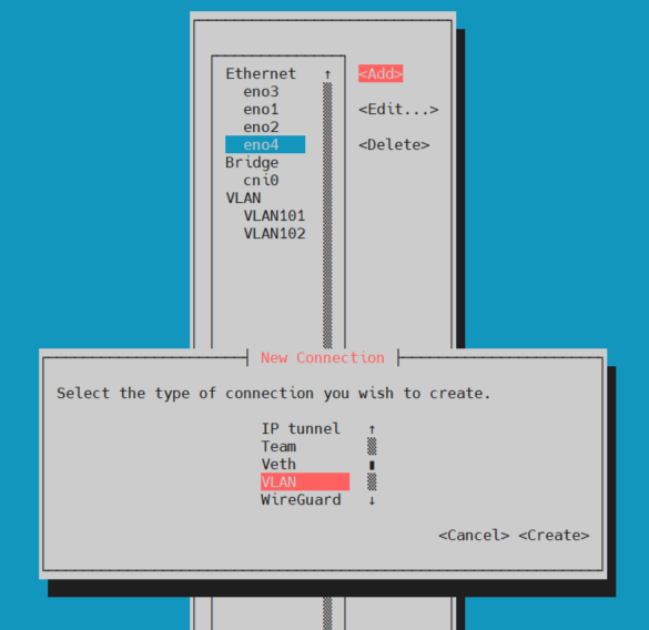
Select 'ADD' then scroll down the list and select 'VLAN'
This will bring up a page for you to configure the VLAN details.
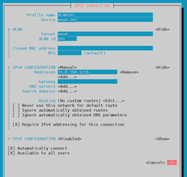
Profile Name - This is the name the ifcfg file will get. I used VLAN101 as it helps me remember what this interface is.
Device - This is the name the VLAN will get, and the name you will refer to it by in EL Configurations. I used interface_name.VLAN_id so eno4.101
Parent - this is the parent interface, we are using eno4 in this example.
VLAN id - Enter your VLAN id here (I am using 101 and in the next example 102)
IPV4 - Fill our your IPv4 Address/Subnet/Gateway etc.
Click OK to save the configuration
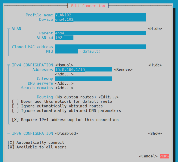
Here are the settings for my second VLAN.
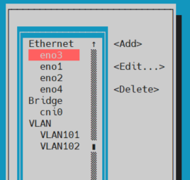
Once you have created your VLANs in nmtui you should see them listed in the main page.
EXIT nmtui.

Reboot the Server.
Once the server has rebooted, navigate to the following directory:
cd /etc/sysconfig/network-scripts
List the files in this directory, and you should see the interface files for the VLANs you created.
ll
total 24
-rw-r--r--. 1 root root 445 Feb 14 14:49 ifcfg-eno1
-rw-r--r--. 1 root root 274 Feb 27 08:34 ifcfg-eno2
-rw-r--r--. 1 root root 274 Feb 28 13:55 ifcfg-eno3
-rw-r--r--. 1 root root 244 Jan  1  2015 ifcfg-eno4
-rw-r--r--. 1 root root 376 Mar 19 15:34 ifcfg-VLAN101
-rw-r--r--. 1 root root 376 Mar 19 14:27 ifcfg-VLAN102
Above we can see the VLAN101 and VLAN102 configuration files have been created.
We can look at the contents of the configuration files using the 'cat' command.
cat ifcfg-VLAN101
VLAN=yes
TYPE=Vlan
PHYSDEV=eno4
VLAN_ID=101
REORDER_HDR=yes
GVRP=no
MVRP=no
HWADDR=
PROXY_METHOD=none
BROWSER_ONLY=no
BOOTPROTO=none
IPADDR=15.0.100.1
PREFIX=16
DEFROUTE=yes
IPV4_FAILURE_FATAL=yes
IPV6_DISABLED=yes
IPV6INIT=no
IPV6_DEFROUTE=yes
IPV6_FAILURE_FATAL=no
IPV6_ADDR_GEN_MODE=default
NAME=VLAN101
UUID=5028382e-2cde-4b1f-ac94-0d77de1910f1
DEVICE=eno4.101
ONBOOT=yes
cat ifcfg-VLAN102
VLAN=yes
TYPE=Vlan
PHYSDEV=eno4
VLAN_ID=102
REORDER_HDR=yes
GVRP=no
MVRP=no
HWADDR=
PROXY_METHOD=none
BROWSER_ONLY=no
BOOTPROTO=none
IPADDR=16.0.100.1
PREFIX=16
DEFROUTE=yes
IPV4_FAILURE_FATAL=yes
IPV6_DISABLED=yes
IPV6INIT=no
IPV6_DEFROUTE=yes
IPV6_FAILURE_FATAL=no
IPV6_ADDR_GEN_MODE=default
NAME=VLAN102
UUID=5b82db81-9074-4e29-bfec-3c7238aaa1c4
DEVICE=eno4.102
ONBOOT=yes
There is one last setting to check (and if you are using an appliance that was created with the corporate ISO then this should be fine).
From the command line, enter the following:
lsmod |grep 8021q
You should see an output similar to below:
8021q                  40960  0
garp                   16384  1 8021q
mrp                    20480  1 8021q
Setting the interface names in Controller
This part does assume that you are familiar with Controller on the Encoder and Multiplexer (you will only be using one or the other)
Now that the VLANs are configured, we need to set those names in Controller to be able to use them. Remember that our VLAN names are:
eno4.101
eno4.102
Open the Controller on your appliance, in this example I am using the output of the Multiplexer.
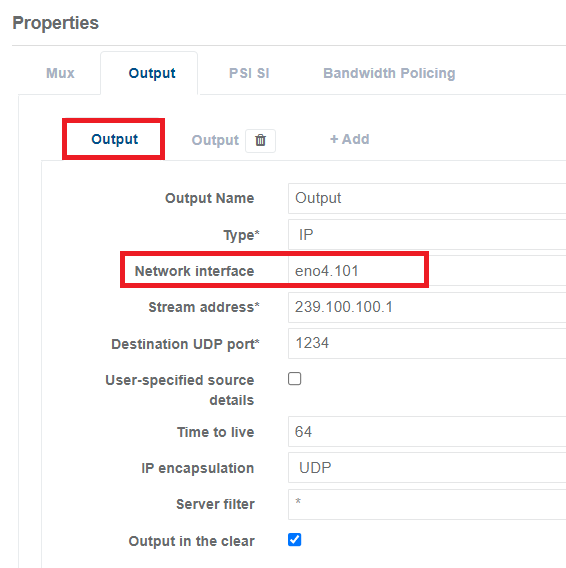
The first Output we are using the interface name eno4.101 The Stream Address is 239.100.100.1. It is important you use the VLAN tag here (eno4.101) and not just the interface name (eno4).
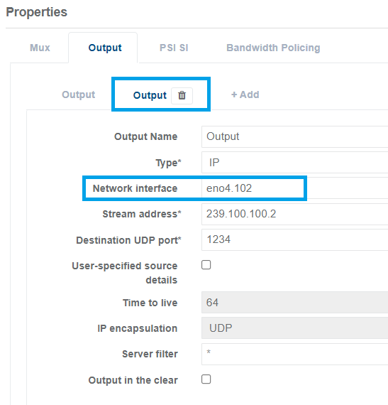
For the second Output we are using the interface name eno4.102 The Stream Address is 239.100.100.2.
Testing the Encoding Live Configuration
Remember, we have two outputs from our system:
eno4.101 239.100.100.1 src 15.0.100.1
eno4.102 239.100.100.2 src 16.0.100.1
We can look for these outputs using tcpdump.
tcpdump -i eno4.101 -nn


listening on eno4.101, link-type EN10MB (Ethernet), capture size 262144 bytes
17:27:01.006691 IP 15.0.100.1.36187 > 239.100.100.1.1234: UDP, length 1316
17:27:01.006709 IP 15.0.100.1.36187 > 239.100.100.1.1234: UDP, length 1316
17:27:01.007661 IP 15.0.100.1.36187 > 239.100.100.1.1234: UDP, length 1316
17:27:01.007693 IP 15.0.100.1.36187 > 239.100.100.1.1234: UDP, length 1316
17:27:01.008649 IP 15.0.100.1.36187 > 239.100.100.1.1234: UDP, length 1316
17:27:01.008668 IP 15.0.100.1.36187 > 239.100.100.1.1234: UDP, length 1316
17:27:01.009774 IP 15.0.100.1.36187 > 239.100.100.1.1234: UDP, length 1316
17:27:01.009793 IP 15.0.100.1.36187 > 239.100.100.1.1234: UDP, length 1316
17:27:01.009808 IP 15.0.100.1.36187 > 239.100.100.1.1234: UDP, length 1316
17:27:01.010699 IP 15.0.100.1.36187 > 239.100.100.1.1234: UDP, length 1316
17:27:01.010715 IP 15.0.100.1.36187 > 239.100.100.1.1234: UDP, length 1316
17:27:01.011659 IP 15.0.100.1.36187 > 239.100.100.1.1234: UDP, length 1316
17:27:01.011682 IP 15.0.100.1.36187 > 239.100.100.1.1234: UDP, length 1316
17:27:01.012649 IP 15.0.100.1.36187 > 239.100.100.1.1234: UDP, length 1316
17:27:01.012666 IP 15.0.100.1.36187 > 239.100.100.1.1234: UDP, length 1316
17:27:01.013685 IP 15.0.100.1.36187 > 239.100.100.1.1234: UDP, length 1316
17:27:01.013703 IP 15.0.100.1.36187 > 239.100.100.1.1234: UDP, length 1316
17:27:01.014651 IP 15.0.100.1.36187 > 239.100.100.1.1234: UDP, length 1316
17:27:01.014668 IP 15.0.100.1.36187 > 239.100.100.1.1234: UDP, length 1316
17:27:01.014698 IP 15.0.100.1.36187 > 239.100.100.1.1234: UDP, length 1316
tcpdump -i eno4.102 -nn


listening on eno4.102, link-type EN10MB (Ethernet), capture size 262144 bytes
17:28:22.773052 IP 16.0.100.1.49656 > 239.100.100.2.1234: UDP, length 1316
17:28:22.773069 IP 16.0.100.1.49656 > 239.100.100.2.1234: UDP, length 1316
17:28:22.774040 IP 16.0.100.1.49656 > 239.100.100.2.1234: UDP, length 1316
17:28:22.774057 IP 16.0.100.1.49656 > 239.100.100.2.1234: UDP, length 1316
17:28:22.775044 IP 16.0.100.1.49656 > 239.100.100.2.1234: UDP, length 1316
17:28:22.775065 IP 16.0.100.1.49656 > 239.100.100.2.1234: UDP, length 1316
17:28:22.776058 IP 16.0.100.1.49656 > 239.100.100.2.1234: UDP, length 1316
17:28:22.776082 IP 16.0.100.1.49656 > 239.100.100.2.1234: UDP, length 1316
17:28:22.776101 IP 16.0.100.1.49656 > 239.100.100.2.1234: UDP, length 1316
17:28:22.777058 IP 16.0.100.1.49656 > 239.100.100.2.1234: UDP, length 1316
17:28:22.777076 IP 16.0.100.1.49656 > 239.100.100.2.1234: UDP, length 1316
17:28:22.778118 IP 16.0.100.1.49656 > 239.100.100.2.1234: UDP, length 1316
17:28:22.778136 IP 16.0.100.1.49656 > 239.100.100.2.1234: UDP, length 1316
17:28:22.779131 IP 16.0.100.1.49656 > 239.100.100.2.1234: UDP, length 1316
17:28:22.779153 IP 16.0.100.1.49656 > 239.100.100.2.1234: UDP, length 1316
17:28:22.780139 IP 16.0.100.1.49656 > 239.100.100.2.1234: UDP, length 1316
17:28:22.780162 IP 16.0.100.1.49656 > 239.100.100.2.1234: UDP, length 1316
17:28:22.781088 IP 16.0.100.1.49656 > 239.100.100.2.1234: UDP, length 1316
17:28:22.781111 IP 16.0.100.1.49656 > 239.100.100.2.1234: UDP, length 1316
17:28:22.781131 IP 16.0.100.1.49656 > 239.100.100.2.1234: UDP, length 1316
It is clear the there is only one set of VLAN tagged traffic on each VLAN output, but all coming from the same physical interface. This is exactly what we want.
Cisco Configuration
For most cases, the customer will be responsible for this, but for this example we will have to configure our own switch, there is not really a lot to do here for a simple test.
We have created two vlan interfaces on our Encoding Live server, and those VLANs will also have to be present on the switch we are connecting to. The interface on the switch will have to be a Trunk Port, the interface on the Encoding Live server is still just an interface for traffic (i.e. it is NOT a trunk port).
Log in to your Cisco switch, and use the following:
Configure the interface to operate in trunk mode using the commands
en
conf t
int gigabitEthernet 0/47 (use your own interface obviously)
switchport mode trunk
That should be it, if you get an error
Command rejected: An interface whose trunk encapsulation is "Auto" can not be configured to "trunk" mode.
You need to manually set the port encapsulation mode: (go back to the top level of the cisco command line first)
en
conf t
int gigabitEthernet 0/47 (use your own interface obviously)
switchport trunk encapsulation dot1q
switchport mode trunk
Now we need to do the following:
Create the same VLANs as on our output device (Encoding Live in this example)
Assign an interface to each VLAN
Below is my current VLAN configuration on the Cisco switch. The interfaces I wish to use (45/46) are currently in VLAN0040. There is no VLAN101 or VLAN102.
VLAN Name                             Status    Ports
---- -------------------------------- --------- -------------------------------
1    default                          active
10   VLAN0010                         active    Gi0/1, Gi0/2, Gi0/3, Gi0/4
                                                Gi0/5, Gi0/6, Gi0/7, Gi0/8
                                                Gi0/9, Gi0/10, Gi0/11, Gi0/12
20   VLAN0020                         active    Gi0/13, Gi0/14, Gi0/15, Gi0/16
                                                Gi0/17, Gi0/18, Gi0/19, Gi0/20
                                                Gi0/21, Gi0/22, Gi0/23, Gi0/24
30   VLAN0030                         active    Gi0/25, Gi0/26, Gi0/27, Gi0/28
                                                Gi0/29, Gi0/30, Gi0/31, Gi0/32
                                                Gi0/33, Gi0/34, Gi0/35, Gi0/36
40   VLAN0040                         active    Gi0/37, Gi0/38, Gi0/39, Gi0/40
                                                Gi0/41, Gi0/42, Gi0/43, Gi0/44
                                                Gi0/45, Gi0/46, Gi0/48
We can create the VLAN and add the interface to it in one line on the cisco:
en
conf t
int gigabitEthernet 0/45
switchport access vlan 101
If the VLAN does not exist, you will see this message:
% Access VLAN does not exist. Creating vlan 101
Repeat these steps for all other required VLANs.
VLAN Name                             Status    Ports
---- -------------------------------- --------- -------------------------------
1    default                          active
10   VLAN0010                         active    Gi0/1, Gi0/2, Gi0/3, Gi0/4
                                                Gi0/5, Gi0/6, Gi0/7, Gi0/8
                                                Gi0/9, Gi0/10, Gi0/11, Gi0/12
20   VLAN0020                         active    Gi0/13, Gi0/14, Gi0/15, Gi0/16
                                                Gi0/17, Gi0/18, Gi0/19, Gi0/20
                                                Gi0/21, Gi0/22, Gi0/23, Gi0/24
30   VLAN0030                         active    Gi0/25, Gi0/26, Gi0/27, Gi0/28
                                                Gi0/29, Gi0/30, Gi0/31, Gi0/32
                                                Gi0/33, Gi0/34, Gi0/35, Gi0/36
40   VLAN0040                         active    Gi0/37, Gi0/38, Gi0/39, Gi0/40
                                                Gi0/41, Gi0/42, Gi0/43, Gi0/44
                                                Gi0/48
101  VLAN0101                         active    Gi0/45
102  VLAN0102                         active    Gi0/46
Above we can see the two new VLANs of 101 and 102, and in these VLANs are the respective interfaces of Gi0/45 and Gi0/46. That should be it, now Save your Cisco configuration.
As per the diagram below:

We should observe now that we can connect to the Multicast 239.0.100.1:1234 when connected to interface 45 on the switch (which has the traffic tagged as 101), but we will not see the Multicast 23.0.100.2:1234 unless we connect to interface 46 on the Cisco switch (which has the traffic tagged as 102).

