Table of Contents
Cisco Inter VLAN Routing
aka Switch Virtual Interfaces (SVI) or Management Interface
Jan 2024
Introduction
Cisco Inter VLAN Routing is the idea that we can communicate between VLANs, where VLANs generally separate network traffic.

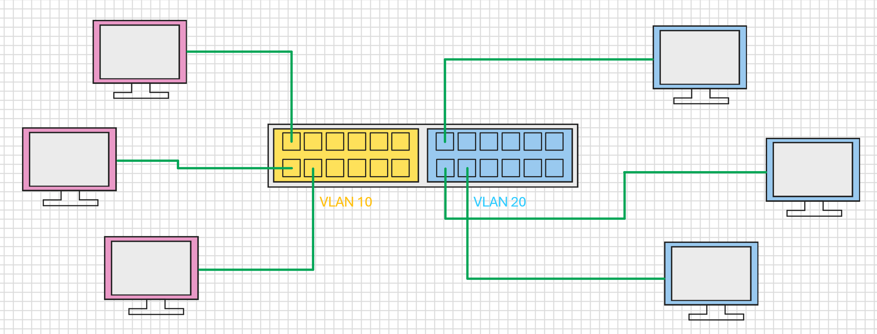
In the example above, we have two VLANs, VLAN 10 and VLAN 20. There are some devices in each VLAN and those devices cannot communicate with each other, they are isolated by the VLAN they occupy.
But what if, for some reason we want them to be able to communicate, we could put them in the same VLAN, but that would increase traffic, and if only one device from each VLAN needs to communicate then putting them all in a single VLAN may not be a great idea.
This is where Inter VLAN Routing can work better.
Setup
We will use an example of two VLANs for this topic. On a new switch all the interfaces will be in VLAN 1. As seen below:
VLAN Name                             Status    Ports
---- -------------------------------- --------- -------------------------------
1    default                          active    Fa0/1, Fa0/2, Fa0/3, Fa0/4
                                                Fa0/5, Fa0/6, Fa0/7, Fa0/8
                                                Fa0/9, Fa0/10, Fa0/11, Fa0/12
                                                Fa0/13, Fa0/14, Fa0/15, Fa0/16
                                                Fa0/17, Fa0/18, Fa0/19, Fa0/20
                                                Fa0/21, Fa0/22, Fa0/23, Fa0/24
                                                Fa0/25, Fa0/26, Fa0/27, Fa0/28
                                                Fa0/29, Fa0/30, Fa0/31, Fa0/32
                                                Fa0/33, Fa0/34, Fa0/35, Fa0/36
                                                Fa0/37, Fa0/38, Fa0/39, Fa0/40
                                                Fa0/41, Fa0/42, Fa0/43, Fa0/44
                                                Fa0/45, Fa0/46, Fa0/47, Fa0/48
1002 fddi-default                     act/unsup
1003 token-ring-default               act/unsup
1004 fddinet-default                  act/unsup
1005 trnet-default                    act/unsup
We need to create some VLANs to separate our devices and the information between them. For this example we can create four VLANs with 12 interfaces in each VLAN.
Creating a VLAN
Follow these steps to create your VLANs (you will need to repeat these steps four times)
Switch1>                          en
Password:                         (enter your switch password)
Switch1#                          conf t
Enter configuration commands, one per line.  End with CNTL/Z.
Switch1(config)#                  int range fastEthernet 0/1-12 (your interface names may differ)
Switch1(config-if-range)#         switchport access vlan 10
% Access VLAN does not exist. Creating vlan 10
Switch1(config-if-range)#         switchport mode access
Switch1(config-if-range)#         spanning-tree portfast
Switch1(config-if-range)#         end
Repeat this to create your VLANs, remember to create at least TWO VLANs.
Check that your VLANs have been created and contain the correct interfaces by using:
sh vlan br

VLAN Name                             Status    Ports
---- -------------------------------- --------- -------------------------------
1    default                          active    Gi0/1, Gi0/2
10   VLAN0010                         active    Fa0/1, Fa0/2, Fa0/3, Fa0/4
                                                Fa0/5, Fa0/6, Fa0/7, Fa0/8
                                                Fa0/9, Fa0/10, Fa0/11, Fa0/12
20   VLAN0020                         active    Fa0/13, Fa0/14, Fa0/15, Fa0/16
                                                Fa0/17, Fa0/18, Fa0/19, Fa0/20
                                                Fa0/21, Fa0/22, Fa0/23, Fa0/24
30   VLAN0030                         active    Fa0/25, Fa0/26, Fa0/27, Fa0/28
                                                Fa0/29, Fa0/30, Fa0/31, Fa0/32
                                                Fa0/33, Fa0/34, Fa0/35, Fa0/36
40   VLAN0040                         active    Fa0/37, Fa0/38, Fa0/39, Fa0/40
                                                Fa0/41, Fa0/42, Fa0/43, Fa0/44
                                                Fa0/45, Fa0/46, Fa0/47, Fa0/48
1002 fddi-default                     act/unsup
1003 token-ring-default               act/unsup
1004 fddinet-default                  act/unsup
1005 trnet-default                    act/unsup
Now we have created our VLANs, you need to ensure you have one device in VLAN 10 and one device in VLAN 20, as shown below:

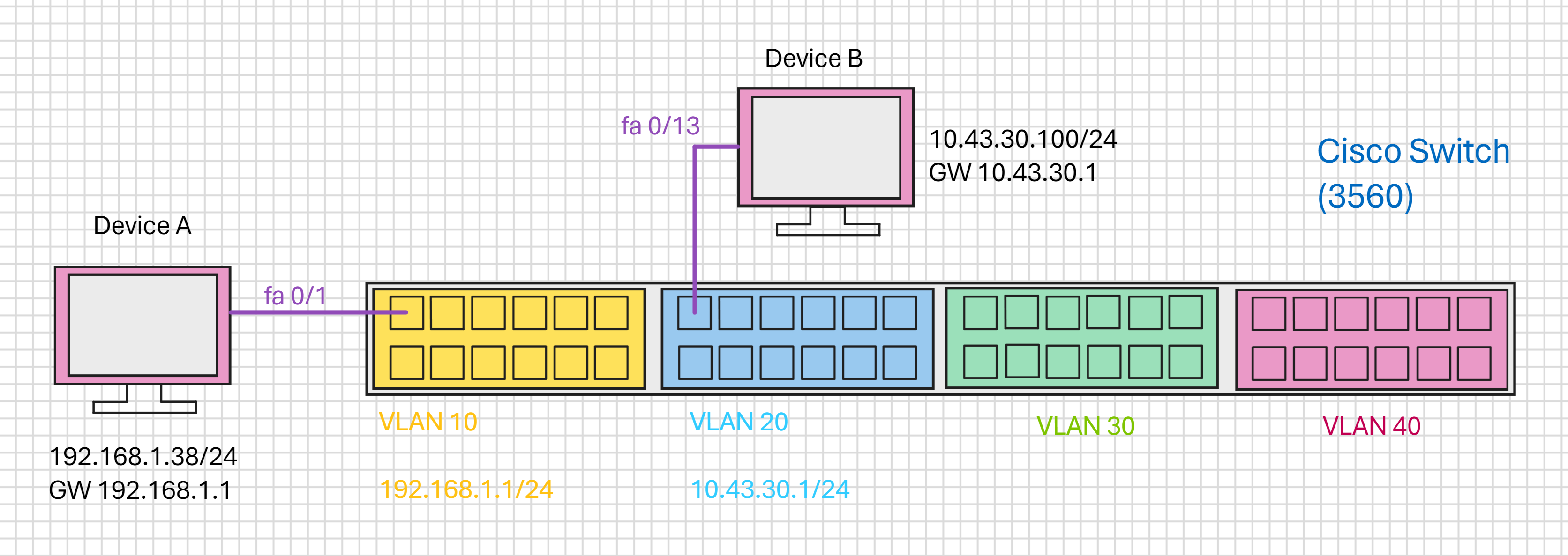
I have connected a device to Interface 1 in VLAN 10 and another device to interface 13 in VLAN 20 (so I am using the first Interface in each VLAN). Of course you can use any interface in the respective VLAN if you wish.
Logical Interfaces
On our switch, if we do a 'sh run' we can see the running config, what we are interested in is likely at or towards the very end of the running config:
sh run

interface Vlan1
 no ip address
 shutdown
What we see here is the Logical Interface for VLAN 1. In this example Interface VLAN1 has no IP Address and is shutdown. Your switch may differ, but with no interfaces in VLAN 1 there is not reason for it to be up or have an IP Address. The main point is that for the VLANs that you created, there is no interface listed (so in my example I see no 'interface VLAN10 or VLAN20 etc).
We need to create some interface VLANs (otherwise known as SVIs (Switch Virtual Interfaces) or Management Interface.
To create the Interface VLANs for VLAN 10 and VLAN 20 follow the steps below:
en
(enter your password for Cisco)
conf t
int vlan 10
ip address 192.168.1.1 255.255.255.0
end
Repeat for other VLANs, then do a 'sh run' and look at the end of the file where virtual interfaces are shown and you will now see virtual interfaces for your VLANs.
sh run

interface Vlan1
 no ip address
 shutdown
!
interface Vlan10
 ip address 192.168.1.1 255.255.255.0
!
interface Vlan20
 ip address 10.43.30.1 255.255.255.0
Above we can now see that VLAN10 and VLAN20 have a virtual interfaces and also have IP Addresses associated with them.
Test Ping from Switch
Now that we have two devices connected to our VLAN and each VLAN has an IP Address in each Subnet, we can Ping our two devices from the Switch Interface:
If you set the VLAN address for example to 192.168.1.1 then this must be the gateway on your device
ping 192.168.1.38

Type escape sequence to abort.
Sending 5, 100-byte ICMP Echos to 192.168.1.38, timeout is 2 seconds:
!!!!!
Success rate is 100 percent (5/5), round-trip min/avg/max = 1/4/9 ms


ping 10.43.30.100

Type escape sequence to abort.
Sending 5, 100-byte ICMP Echos to 10.43.30.100, timeout is 2 seconds:
!!!!!
Success rate is 100 percent (5/5), round-trip min/avg/max = 1/5/16 ms
NOTE, if you cannot PING, ensure that the firewall is disabled on the devices for this test
IP Routing
As a quick reminder, here is a diagram of the network we are using:

Before we look at the configuration of IP Routing, lets do a test ping from Device A (192.168.1.38) to Device B (10.43.30.100):
ping 10.43.30.100

Pinging 10.43.30.100 with 32 bytes of data:
Request timed out.
Request timed out.
Request timed out.
Request timed out.

Ping statistics for 10.43.30.100:
    Packets: Sent = 4, Received = 0, Lost = 4 (100% loss),
As can be seen from the above output, the PING failed, which is good because without actually setting up any IP Routing this is what we would expect and want.
To enable IP Routing on the switch, we will use the following:
en
conf t
ip routing
end
There is no text return from running this command.
No we can test to see the routes by using the following:
sh ip route

Codes: C - connected, S - static, R - RIP, M - mobile, B - BGP
       D - EIGRP, EX - EIGRP external, O - OSPF, IA - OSPF inter area
       N1 - OSPF NSSA external type 1, N2 - OSPF NSSA external type 2
       E1 - OSPF external type 1, E2 - OSPF external type 2
       i - IS-IS, su - IS-IS summary, L1 - IS-IS level-1, L2 - IS-IS level-2
       ia - IS-IS inter area, * - candidate default, U - per-user static route
       o - ODR, P - periodic downloaded static route

Gateway of last resort is not set

     10.0.0.0/24 is subnetted, 1 subnets
C       10.43.30.0 is directly connected, Vlan20
C    192.168.1.0/24 is directly connected, Vlan10
We can see that the two interface VLANs are shown (10.43.30.0 is directly connected, Vlan20 and 192.168.1.0/24 is directly connected, Vlan10).
Now try to ping from Device A (192.168.1.38) to Device B (10.43.30.100). Remember, the gateway of Device A must be the IP Address of VLAN 10 (192.168.1.1 in this example).
Pinging 10.43.30.100 with 32 bytes of data:
Reply from 10.43.30.100: bytes=32 time<1ms TTL=127
Reply from 10.43.30.100: bytes=32 time=1ms TTL=127
Reply from 10.43.30.100: bytes=32 time=1ms TTL=127
Reply from 10.43.30.100: bytes=32 time<1ms TTL=127
Now we can communicate with devices in VLAN 20 from VLAN 10.
